With the advent of new methods for redundancy and reliability, the need for UPS (Uninterruptible Power System) Energy Storage Solutions has changed. Thirty years ago, UPSs were intended to be used as backup power to provide time for an orderly “Systematic Shutdown” of computing systems whenever there was a utility power disturbance. The time required for the UPS to continue to provide power (after an outage) was based on how long it took to stop all processes without negatively affecting data integrity or losing any data. This was when the economy allowed businesses to be able to stop computing/data processing. Even with on-site generators, the old technology generators took minutes to gain enough speed and voltage to carry the load, requiring minutes of bridging time from the UPS.
In today’s worldwide internet economy, businesses cannot afford downtime. Any downtime — seconds to minutes — not only results in a company losing revenues but also allows its competition to gain an advantage. A consumer or a business will immediately look for alternatives upon any sign of inability to complete a transaction. This failure to complete a transaction can occur because a site is down – be it credit card (VISA, MC, AE), distribution (Grainger, Amazon, Mouser, etc.), retail (Best Buy, Vons), or financial service providers.
Traditional Backup Configurations
To reduce downtime, most data centers and other mission-critical operations employ on-site power systems with N+1, 2N, 2N+1, or one of the many reserve power configurations. Such systems usually consist of generators, UPSs, and static switches. Some of the traditional configurations are shown in Figures 1, 2 and 3.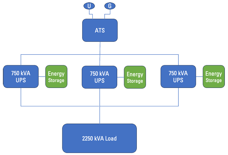
Figure 1. N Configuration is the most vulnerable configuration that is not fault tolerant
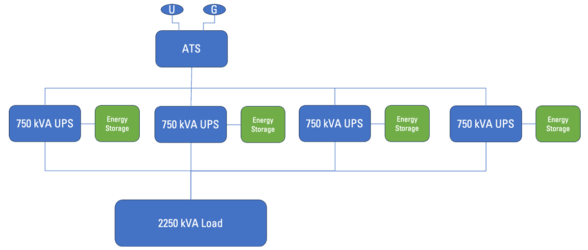
Figure 2. N+1 Configuration, an additional UPS provides minimal redundancy
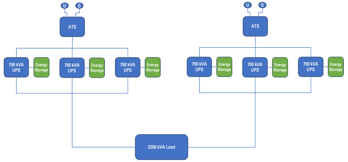
Figure 3. 2N Configuration, an additional N system provides more redundancy than N+1
In the past, large data center designs called for large banks of generators connected to the generator bus. Sometimes, as many as 12 generators had to be initiated and synchronized with the first generator on-line before they could be linked to the generator bus. This meant that while the first generator would be on-line in 10 to 15 seconds, each additional generator would take another 10 to 15 seconds to start, synchronize, and close its breaker to the generator bus. All generators would have to be on the bus, before critical loads would start to be reconnected to the backup power system. This required the UPS to have a requirement for longer autonomy as well. Today, many data centers with distributed redundant designs do not require the generators to be paralleled before connecting to the bus. Each generator serves a single UPS or a group of UPSs and can be on-line 10 to 15 seconds after a utility outage occurs.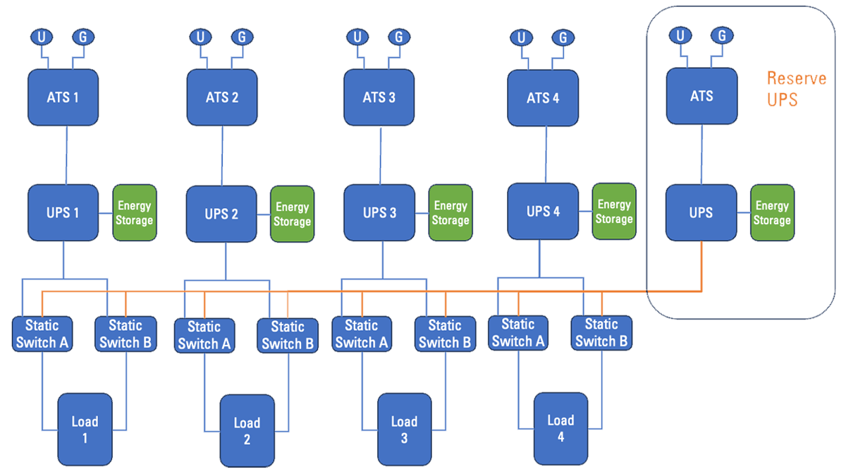
Figure 4. Shared Reserve Backup Configuration
A reserve UPS can be used to support a single client or multiple clients. Figure 4 shows a shared reserve configuration utilizing a reserve UPS that can support multiple clients (load X represents multiple clients). While modern power systems reduce the risk of downtime, the need for energy storage still exists. Energy storage is used for those times when bridge time is needed – to bridge the power between utility failure and the 10 to 15 seconds it takes for emergency power to become available, usually with on-site generators. With these new reliability and reserve power configurations, 15- to 30-minute battery systems are no longer necessary. In fact, essential electrical systems as defined in NFPA 99 (Health Care Facilities Code), “shall be classified as Type 10, Class X Level 1 generator sets per NFPA 110.” The Type 10 designation in NFPA 110 defines the maximum “time, in seconds that the Emergency Power Supply Systems (EPSS) will permit the load terminals of the transfer switch to be without electrical power.” In the case of Type 10, the maximum time is 10 seconds.Out with the Old and In with the New
Evolution in supercapacitor technology presents an attractive alternative to battery (Li-ION, VRLA, Sodium or Zinc-based) solutions. A great example of these advancements is Musashi Energy Solutions’ (MES) Hybrid SuperCapacitor (HSC) based solution for the bridging needs of the modern Emergency Power Supply System. MES’ Hybrid SuperCapacitors (HSC) are a compelling solution for the bridging needs of the modern emergency power supply system. MES takes the best of the Electric Dual Layer Capacitor (EDLC) (High Power Density) and Li-Ion batteries (High Energy Density) without the thermal runaway (fire) issues. Musashi’s ESS400 is an HSC-based energy storage system capable of delivering up to 400kW of power in a compact cabinet. Suitable for UPSs up to 400 kW, it can be paralleled for higher power capacity, longer bridging time, or for redundancy. No longer is there a need for conventional batteries, whether valve-regulated lead acid (VRLA) or Lithium-based – prone to short life with disposal issues or thermal runaway risks. The ESS400 utilizes a proven HSC technology that has been in production for many years. It operates at a nominal voltage of 480V DC, with an operating range of 594-384 VDC, suitable for use with most 3-phase UPSs. The old method of using VRLAs in multiple cabinets, taking up valuable floor space, and providing 15-plus minutes of backup power is no longer needed. New methods in technology and power system methodology (reliability and redundancy) have paved the way for more cost-effective energy storage solutions that include longer life and higher cycle life without the risk of thermal runaway and no disposal issues. For additional detailed comparison information, please visit: https://musashienergysolutions.com/ess400-hybrid-supercapacitor-from-musashi-energy-solutions/.Download a printable/shareable PDF of this Application Note here.